|
Size: 15336
Comment:
|
Size: 15757
Comment: removed toolbar icon for URL import
|
| Deletions are marked like this. | Additions are marked like this. |
| Line 8: | Line 8: |
| Network files can be specified in any of the formats described in the [[Cytoscape_User_Manual/Network_Formats|Supported Network Formats]] chapter. | Network files can be specified in any of the formats described in the '''[[Cytoscape_User_Manual/Network_Formats|Supported Network Formats]]''' section. |
| Line 19: | Line 19: |
|
You also need to designate which columns represent source and target nodes, and you can also designate the type of interaction. Clicking on the header of any column will bring up an interface for where you can select source and target node, as well as interaction type. {{attachment:ImportNetworkDialog2.png}} |
|
| Line 22: | Line 26: |
| To load a network from a remote file, you can select '''File → Import → Network → URL...''' or click on {{attachment:Cy3_icon_net_url_import.png}} on the tool bar. In the import network dialog, insert the appropriate URL, either manually or using URL bookmarks. Bookmarked URLs can be accessed by clicking on the arrow to the right of the text field (see the Bookmark Manager in [[Cytoscape_User_Manual/Preferences|Preferences]] for more details on bookmarks). Also, you can drag and drop links from a web browser to the URL text box. Once a URL has been specified, click on the OK button to load the network. | To load a network from a remote file, you can select '''File → Import → Network → URL...'''. In the import network dialog, insert the appropriate URL, either manually or using URL bookmarks. Bookmarked URLs can be accessed by clicking on the arrow to the right of the text field (see the Bookmark Manager in [[Cytoscape_User_Manual/Preferences|Preferences]] for more details on bookmarks). Also, you can drag and drop links from a web browser to the URL text box. Once a URL has been specified, click on the OK button to load the network. |
| Line 26: | Line 30: |
| Another issue for network import is the presence of firewalls, which can affect which files are accessible to a computer. To work around this problem, Cytoscape supports the use of proxy servers. To configure a proxy server, go to '''Edit → Preferences→ Proxy Settings...'''. This is further described in the [[Cytoscape_User_Manual/Preferences|Preferences]] chapter. | Another issue for network import is the presence of firewalls, which can affect which files are accessible to a computer. To work around this problem, Cytoscape supports the use of proxy servers. To configure a proxy server, go to '''Edit → Preferences→ Proxy Settings...'''. This is further described in the '''[[Cytoscape_User_Manual/Preferences|Preferences]]''' section. |
| Line 67: | Line 71: |
| The network import function cannot import node table columns - only edge table columns. To import node table columns from this table, please see the [[Cytoscape_User_Manual/TableColumnData|Table Column Data]] section of this manual. | The network import function cannot import node table columns - only edge table columns. To import node table columns from this table, please see the '''[[Cytoscape_3/UserManual/Columns|Node and Edge Column Data]]''' section of this manual. |
| Line 86: | Line 90: |
| The table import feature supports lists of nodes without edges. If you select only a source column, it creates a network without interactions. This feature is useful with the node expansion function available from some web service clients. Please read the section ''[[Cytoscape_User_Manual/ImportingNetworksFromWebServices|Importing Networks from External Database]]'' for more detail. | The table import feature supports lists of nodes without edges. If you select only a source column, it creates a network without interactions. This feature is useful with the node expansion function available from some web service clients. Please read the section '''[[Cytoscape_User_Manual/ImportingNetworksFromWebServices|Importing Networks from External Database]]''' for more detail. |
| Line 123: | Line 127: |
|
=== Web Service Client Manager === Cytoscape has a feature called '''Web Service Client Manager'''. This is a framework to manage various kinds of web service clients in Cytoscape. By using web service clients, users can access remote data sources easily. |
{{{#!wiki comment |
| Line 134: | Line 136: |
|
* [[http://code.google.com/p/psicquic/|PSICQUIC]]: Standard web service for biological interaction data sets. The following data providers support PSICQUIC: * APID * Bar * BIND * BindingDB * GeneMANIA * I2Z-IMEX * ChEMBL * BioGrid * InnateDB * InnateDB-IMEx * Interoporc * MB-Info * Molcon * Spike * TopFind * uniProt * VirHostNet * DIP * IntAct * MatrixDB * MPIDB * Reactome * Reactome-FIs * MINT * iRefIndex * STRING |
* [[http://code.google.com/p/psicquic/|PSICQUIC]]: Standard web service for biological interaction data sets. The full list of PSICQUIC-compatible databases is available [[http://www.ebi.ac.uk/Tools/webservices/psicquic/registry/registry?action=STATUS|here]]. |
| Line 164: | Line 139: |
| }}} | |
| Line 172: | Line 147: |
| === Example #1: Retrieving Protein-Protein Interaction Networks from Multiple Databases === | === Example: Retrieving Protein-Protein Interaction Networks from Multiple Databases === |
| Line 202: | Line 177: |
|
== Adding a Node == To add a new node, right-click on an empty space of the network view panel. Select '''Add → Node''' item from the pop-up menu. Image below shows the right click menu for creating a new node. {{attachment:Figure1_Editor_Cy3.png}} == Adding an Edge == To add an edge to connect nodes, right-click on the source node. Select '''Edit → Add Edge''' from the pop-up menu. Next, click on the target node. Images below show the two steps for drawing an edge between two nodes. You can abort the drawing of the edge by pressing Esc key. You can also select the two nodes to connect and in the right-click menu select select '''Add → Edges Connecting Selected Nodes'''. {{attachment:Figure2_Editor_Cy3.png}} {{attachment:Figure3_Editor_Cy3.png}} {{attachment:Figure4_Editor_Cy3.png}} You can delete nodes and edges by selecting a number of nodes and edges, then selecting '''Edit → Delete Selected Nodes and Edges'''. You can recover any nodes and edges deleted from a network by going to '''Edit → Undo'''. == Grouping nodes == |
=== Adding a Node === To add a new node, right-click on an empty space of the network view panel. Select '''Add → Node''' item from the pop-up menu. {{attachment:AddNodeMenu.png}} === Adding an Edge === To add an edge to connect nodes, right-click on the source node. Select '''Edit → Add Edge''' from the pop-up menu. Next, click on the target node. The Images below show the two steps for drawing an edge between two nodes. You can abort the drawing of the edge by pressing Esc key. You can also select two or more nodes to connect and in the right-click menu select '''Add → Edges Connecting Selected Nodes''' to create edges connecting all selected nodes. {{attachment:AddEdgeMenu.png}} {{attachment:AddEdge-2.png}} You can delete nodes and edges by selecting a number of nodes and edges, then selecting '''Edit → Cut'''. You can also delete selected nodes and edges from the '''Edit''' menu, under '''Edit → Delete Selected Nodes and Edges...'''. You can recover any nodes and edges deleted from a network by going to '''Edit → Undo'''. === Grouping nodes === |
| Line 225: | Line 198: |
|
{{attachment:GroupCollapsed.png}} {{attachment:GroupExpanded.png}} |
'''Collapsed group''' {{attachment:GroupCollapsed.png|400px|Collapsed group}} '''Expanded group''' {{attachment:GroupExpanded.png|400px|Expanded group}} === Adding Network Annotations === Annotations in the form of text, images or shapes can be added to the network canvas by right-clicking anywhere on the canvas and selecting one of the Annotation choices in the '''Add''' menu. You can add an image of your own, choose from a shapes library or add either plain or bounded text. Shapes and text are customizable and any added annotations can be edited from the right-click context menu. {{attachment:AddNetworkAnnotations.png|Add Network Annotations}} |
There are 4 different ways of creating networks in Cytoscape:
- Importing pre-existing, fixed-format network files.
- Importing pre-existing, unformatted text or Excel files.
- Importing data from from public databases.
- Creating an empty network and manually adding nodes and edges.
Import Fixed-Format Network Files
Network files can be specified in any of the formats described in the Supported Network Formats section. Networks are imported into Cytoscape through the File → Import → Network menu. The network file can either be located directly on the local computer, or found on a remote computer (in which case it will be referenced with a URL).
Load Networks from Local Computer
In order to load a network from a local file you can select File → Import → Network → File... or click on ![]() on the tool bar. Choose the correct file in the file chooser dialog and press Open. Some sample network files of different types have been included in the sampleData folder in Cytoscape.
on the tool bar. Choose the correct file in the file chooser dialog and press Open. Some sample network files of different types have been included in the sampleData folder in Cytoscape.
After you choose a network file, another dialog will pop up. Here, you can choose either to create a new network collection for the new network, or load the new network into an existing network collection. When you choose the latter, make sure to choose the right mapping column to map the new network to the existing network collection.
You also need to designate which columns represent source and target nodes, and you can also designate the type of interaction. Clicking on the header of any column will bring up an interface for where you can select source and target node, as well as interaction type.
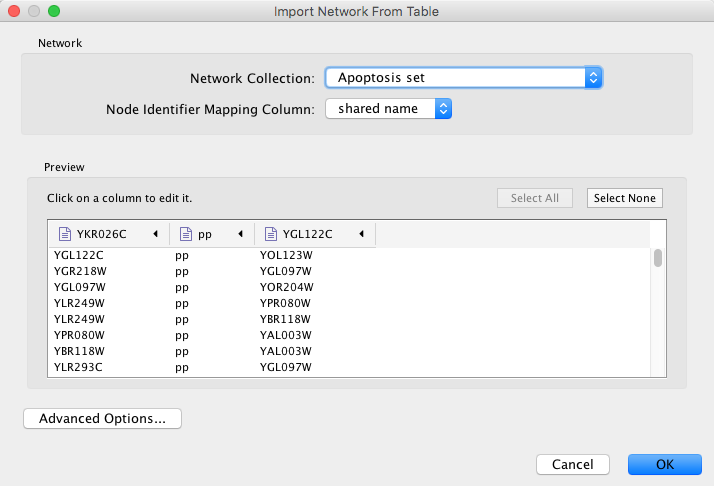
Network files in SIF, GML, and XGMML formats may also be loaded directly from the command line using the –N option.
Load Networks from a Remote Computer (URL import)
To load a network from a remote file, you can select File → Import → Network → URL.... In the import network dialog, insert the appropriate URL, either manually or using URL bookmarks. Bookmarked URLs can be accessed by clicking on the arrow to the right of the text field (see the Bookmark Manager in Preferences for more details on bookmarks). Also, you can drag and drop links from a web browser to the URL text box. Once a URL has been specified, click on the OK button to load the network.

Another issue for network import is the presence of firewalls, which can affect which files are accessible to a computer. To work around this problem, Cytoscape supports the use of proxy servers. To configure a proxy server, go to Edit → Preferences→ Proxy Settings.... This is further described in the Preferences section.
Import Networks from Unformatted Table Files
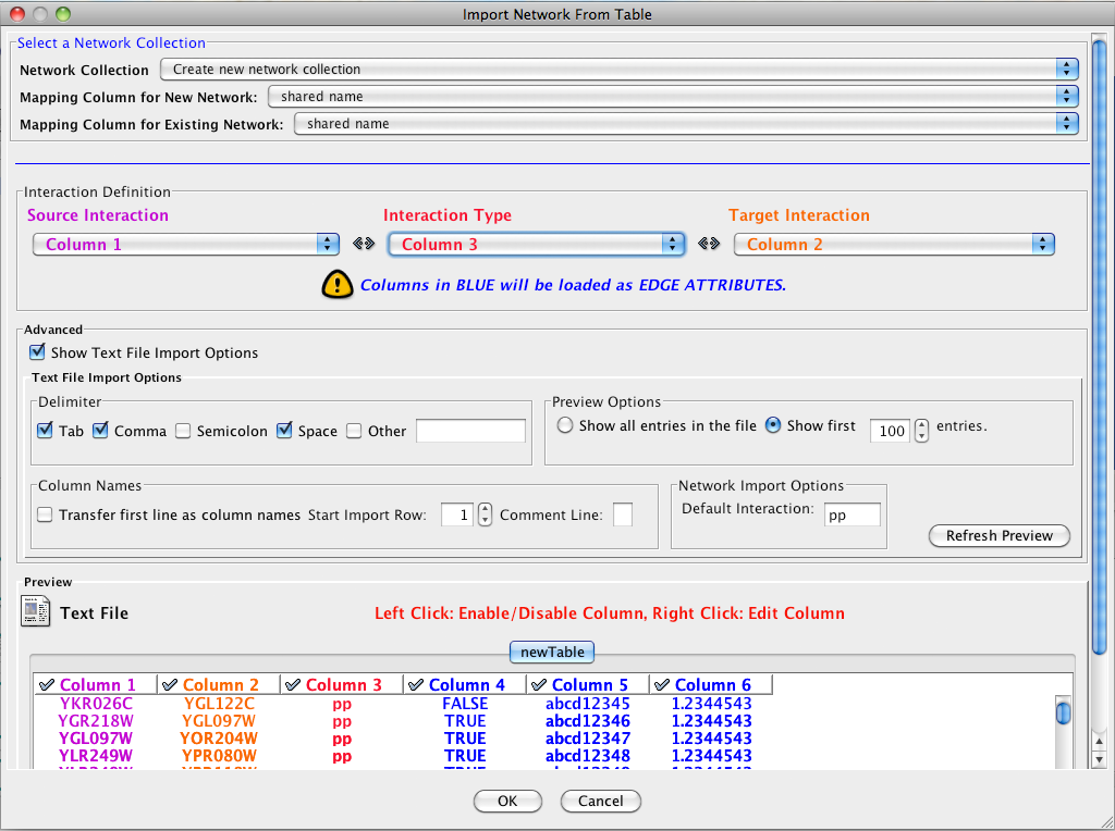
Cytoscape supports the import of networks from delimited text files and Excel workbooks using File → Import → Network → File.... An interactive GUI allows users to specify parsing options for specified files. The screen provides a preview that shows how the file will be parsed given the current configuration. As the configuration changes, the preview updates automatically. In addition to specifying how the file will be parsed, the user must also choose the columns that represent the source and target nodes as well as an optional edge interaction type.
Supported Files
The Import Network from Table function supports delimited text files and single-sheet Microsoft Excel Workbooks. The following is a sample table file:
source  target  interaction  boolean data       string data     floating point data
YJR022W YNR053C pp      TRUE    abcd12371       1.2344543
YER116C YDL013W pp      TRUE    abcd12372       1.2344543
YNL307C YAL038W pp      FALSE   abcd12373       1.2344543
YNL216W YCR012W pd      TRUE    abcd12374       1.2344543
YNL216W YGR254W pd      TRUE    abcd12375       1.2344543
The network table files should contain at least two columns for creating network with edges. If the file has only one column, the created network will not contain any edges. The interaction type is optional in this format. Therefore, a minimal network table looks like the following:
YJR022W YNR053C
YER116C YDL013W
YNL307C YAL038W
YNL216W YCR012W
YNL216W YGR254W
One row in a network table file represents an edge and its edge data columns. This means that a network file is considered a combination of network data and edge column data. A table may contain columns that aren't meant to be edge data. In this case, you can choose not to import those columns by clicking on the column header in the preview window. This function is useful when importing a data table like the following (1):

This data file is a tab-delimited text file and contains network data (interactions), edge data, and node data. To import network and edge data from this table, choose Unique ID A as source, Unique ID B as target, and Interactor types as interaction type. Next, turn off columns used for node data (Alternative ID A, species B, etc.). Other columns can be imported as edge data.
The network import function cannot import node table columns - only edge table columns. To import node table columns from this table, please see the Node and Edge Column Data section of this manual.
Note (1): This data is taken from the A merged human interactome datasets by Andrew Garrow, Yeyejide Adeleye and Guy Warner (Unilever, Safety and Environmental Assurance Center, 12 October 2006). Actual data files are available at http://www.cytoscape.org/cgi-bin/moin.cgi/Data_Sets/
Basic Operations
To import network from text/Excel tables, please follow these steps:
Select File → Import → Network → File... or click on
 on the tool bar.
 - Select a table file in the file chooser dialog.
Define the interaction parameters by specifying which columns of data contain the Source Interaction, Target Interaction, and Interaction Type. Setting the Interaction Type as Default Interaction will result in all interactions being given the value pp; this value can be modified in Advanced Options (below).
- (Optional) Define edge table columns, if applicable. Network table files can have edge table columns in addition to network data.
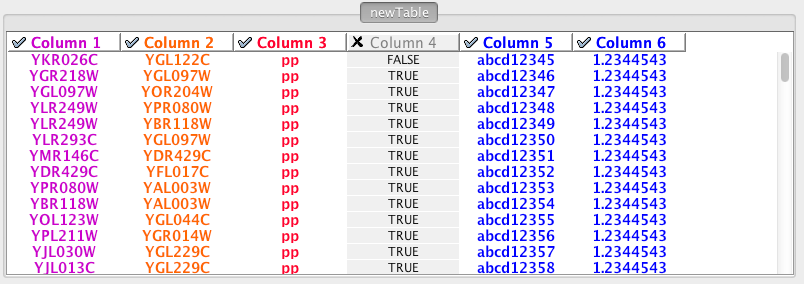
Enable/Disable Table Columns - By left-clicking on a column header in the preview table, you can enable/disable edge column data. If the header is checked and entries are blue, the column will be imported as an edge column data. For example, the table below shows that columns 1 through 3 will be used as network data, column 4 will not be imported, and columns 5 and 6 will be imported as edge table column data.
Change Column Name and Data Types - If you right-click on a column header in the preview table, you can modify the column name and data type. For more detail, see Modify Column Name/Type below.
- Click the Import button.
Import List of Nodes Without Edges
The table import feature supports lists of nodes without edges. If you select only a source column, it creates a network without interactions. This feature is useful with the node expansion function available from some web service clients. Please read the section Importing Networks from External Database for more detail.
Advanced Options

You can select several options by checking the Show Text File Import Options checkbox.
- Delimiter: You can select multiple delimiters for text tables. By default, Tab and Space are selected as delimiters.
Preview Options: When you select a network table file, the first 100 entries will be displayed in the preview panel. To display more entries, change the value for this option. If you want to show all entries in the file, select Show all entries in the file. You will need to click the Reload button to update the Preview panel.
- Column Names
- Transfer first line as column names: Selecting this option will cause all edge columns to be named according to the first data entry in that column.
- Start Import Row: Set which row of the table to begin importing data from. For example, if you want to skip the first 3 rows in the file, set 4 for this option.
- Comment Line: Rows starting with this character will not be imported. This option can be used to skip comment lines in text files.
Network Import Options: If the Interaction Type is set to Default Interaction, the value here will be used as the interaction type for all edges.
Modify Column Name/Type
In the Import Network from Table interface, you can change the name and data type of column by right-clicking on any column header:
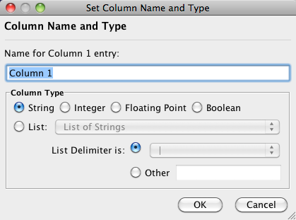
Column names and data types can be modified here.
- Modify Column Name - just enter a new column name and click OK.
- Modify Column Data Type - The following column data types are supported:
- String
- Boolean (True/False)
- Integer
- Floating Point
- List of (one of) String/Boolean/Integer/Floating Point
Cytoscape has a basic data type detection function that automatically suggests the column data type according to its entries. This can be overridden by selecting the appropriate data type from the radio buttons provided. For lists, a global delimiter must be specified (i.e., all cells in the table must use the same delimiter).
Import Networks from Public Databases
Cytoscape has a feature called Import Network from Public Databases. Users can access various kinds of databases through this function, File → Import → Network → Public Databases....
Getting Started
To get started, select File → Import → Network → Public Databases....
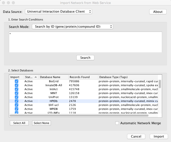
Example: Retrieving Protein-Protein Interaction Networks from Multiple Databases
Select File → Import → Network → Public Databases....
From the pull-down menu, select the Interaction databases Universal Client.
- Enter one or more search terms, such as BRCA1.
Click the Search button to start the search.
- Select databases from the hits. This selection will be saved as your default database list.
Click the Import button to import selected network data.
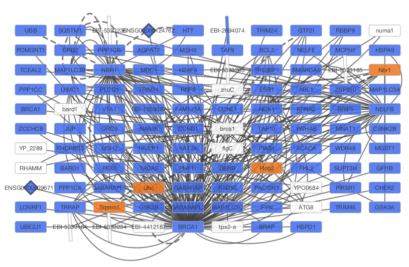
After confirming the download of interaction data, the network of BRCA1 will be imported and visualized.
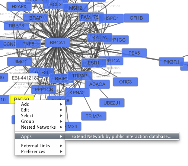
Tip: Expanding the Network: Several of the Cytoscape web services provide additional options in the node context menu. To access these options, right-click on a node and select Apps → Extend Network by public interaction database.... For example, in the screenshot, we have loaded the BRCA1 network from IntAct, and have chosen to merge this node's neighbors into the existing network.
PSICQUIC Options
PSICQUIC Web Service Client has three search modes:
- Search by ID
- Search by MIQL
- Search by Species
By default, search mode is set to Search by ID. You can search all databases by ID, such as gene symbol, Uniprot ID, or NCBI gene ID. If the search mode is set to MIQL, you can use MIQL for search. If you want to search interactions by keywords or specific functions, this is the powerful query language to filter the result. The last option is for importing all interactions for the species (i.e., interactome).
Create a New Network Manually
A new, empty network can also be created and nodes and edges manually added. To create an empty network, go to File → New → Network → Empty Network, and then manually add network components by right clicking on the network canvas or on a node.
Adding a Node
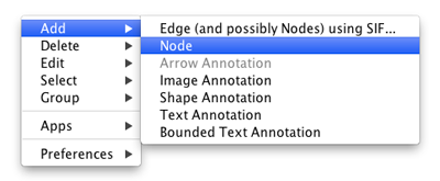
To add a new node, right-click on an empty space of the network view panel. Select Add → Node item from the pop-up menu.
Adding an Edge
To add an edge to connect nodes, right-click on the source node. Select Edit → Add Edge from the pop-up menu. Next, click on the target node. The Images below show the two steps for drawing an edge between two nodes. You can abort the drawing of the edge by pressing Esc key. You can also select two or more nodes to connect and in the right-click menu select Add → Edges Connecting Selected Nodes to create edges connecting all selected nodes.
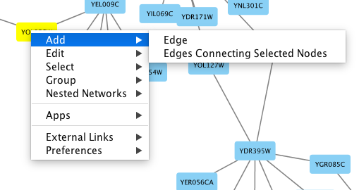
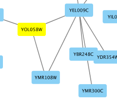
You can delete nodes and edges by selecting a number of nodes and edges, then selecting Edit → Cut. You can also delete selected nodes and edges from the Edit menu, under Edit → Delete Selected Nodes and Edges.... You can recover any nodes and edges deleted from a network by going to Edit → Undo.
Grouping nodes
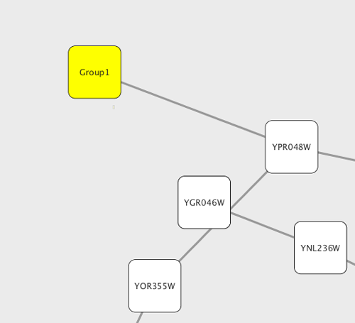
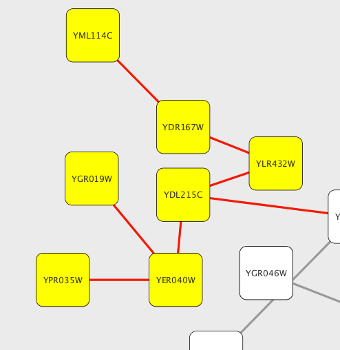
Any number of nodes can be grouped together and displayed as either one group node or as the individual nodes. To create a group, select two or more nodes and right-click to select Group → Group Selected Nodes. You will be prompted to select a name for the group node. Once a group is created, you can use the right-click menu to collapse or expand the group. You can also quickly collapse/expand a group by double-clicking on the group node or any of its children to toggle back and forth.
Collapsed group
Expanded group
Adding Network Annotations
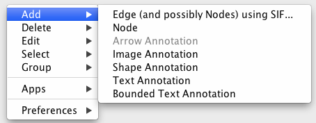
Annotations in the form of text, images or shapes can be added to the network canvas by right-clicking anywhere on the canvas and selecting one of the Annotation choices in the Add menu. You can add an image of your own, choose from a shapes library or add either plain or bounded text. Shapes and text are customizable and any added annotations can be edited from the right-click context menu.
