|
Size: 18161
Comment: removed referenced to "visual style"
|
Size: 18670
Comment:
|
| Deletions are marked like this. | Additions are marked like this. |
| Line 4: | Line 4: |
| Cytoscape uses a [[http://en.wikipedia.org/wiki/Zooming_User_Interface|Zoomable User Interface]] for navigating and viewing networks. ZUIs use two mechanisms for navigation: zooming and panning. Zooming increases or decreases the magnification of a view based on how much or how little a user wants to see. Panning allows users to move the focus of a screen to different parts of a view. | Cytoscape uses a [[http://en.wikipedia.org/wiki/Zooming_User_Interface|Zoomable User Interface]] for navigating and viewing networks. ZUIs use two mechanisms for navigation: zooming and panning. Zooming increases or decreases the magnification of a view based on how much or how little a user wants to see. Panning allows users to move the focus of a screen to different parts of a view. |
| Line 25: | Line 25: |
| * Dragging Box on Network Overview - You can also pan the image by holding down the left mouse button over the blue box in the overview panel in the lower part of the Network tab in the Control Panel. | * Dragging Box on '''[[Cytoscape_3/UserManual/Quick_Tour#NetworkOverview|Network Overview]]''' - You can also pan the image by holding down the left mouse button over the blue box in the overview panel in the lower part of the Network tab in the Control Panel. |
| Line 35: | Line 35: |
| This menu can change based on the current context. For nodes, it typically shows: |
This menu can change based on the current context. For nodes, it typically shows: * Add |
| Line 46: | Line 47: |
|
* Select * Apps |
|
| Line 47: | Line 50: |
|
Apps can contribute their own items into node and edge context menus. These additions usually appear in the '''''Apps''''' menu. ===== Nested Network Node Context Submenu ===== !!! menu items changed names |
* Preferences Apps can contribute their own items into node and edge context menus. These additions usually appear in the '''Apps''' section of the context menu. ===== Nested Network Node Context Menu ===== |
| Line 53: | Line 56: |
| Lets the user select any network in Cytoscape as the current node's nested network. If the current node already has a nested network it will be replaced. | Lets the user select any network in Cytoscape as the current node's nested network. If the current node already has a nested network it will be replaced. |
| Line 55: | Line 58: |
| After being selected the current node will no longer have a nested network associated with it. The associated network is not deleted. Only the association between the node and the network is removed. | Removes the currently associated nested network from a node. The associated network is not deleted. Only the association between the node and the network is removed. |
| Line 57: | Line 60: |
|
After selecting this the network view of the current node's nested network will be the current network view and have the focus. Should a network view for the nested network not exist, it will be created. |
The current node's nested network will be the current network view and have the focus. Should a network view for the nested network not exist, it will be created. More information about nested networks can be found in the '''[[Cytoscape_3/UserManual/Nested_Networks|Nested Networks]]''' section. |
| Line 61: | Line 65: |
| The Layout menu has an array of features for organizing the network visually according to one of several algorithms, aligning and rotating groups of nodes, and adjusting the size of the network. Cytoscape layouts have three different sources, which are reflected in the '''''Layout''''' menu. |
The Layout menu has an array of features for organizing the network visually according to one of several algorithms, aligning and rotating groups of nodes, and adjusting the size of the network. Cytoscape layouts have three different sources, which are reflected in the '''Layout''' menu. With the exception of the '''yFiles''' layouts (explained below), Cytoscape Layouts have the option to operate on only the selected nodes, and all provide a '''Settings...''' panel to change the parameters of the algorithm. Most of the Cytoscape layouts also partition the graph before performing the layout. In addition, many of these layouts include the option to take either node or edge columns into account. A few of the layout algorithms are: ==== Grid Layout ==== {{attachment:grid_layout.png}} The grid layout is a simple layout the arranges all of the nodes in a square grid. This is the default layout and is always available as part of the Cytoscape core. It is available by selecting '''Layout → Grid Layout'''. A sample screen shot is shown above. ==== Edge-weighted Spring-Embedded Layout ==== {{attachment:spring.png}} The spring-embedded layout is based on a “force-directed” paradigm as implemented by Kamada and Kawai (1988). Network nodes are treated like physical objects that repel each other, such as electrons. The connections between nodes are treated like metal springs attached to the pair of nodes. These springs repel or attract their end points according to a force function. The layout algorithm sets the positions of the nodes in a way that minimizes the sum of forces in the network. This algorithm can be applied to the entire network or a portion of it by selecting the appropriate options from '''Layout → Edge-weighted Spring Embedded'''. ==== Attribute Circle Layout ==== {{attachment:attribute_circle_layout.png}} The '''Attribute Circle''' layout is a quick, useful layout, particularly for small networks, that will locate all of the nodes in the network around a circle. The node order is determined by a user-selected node column. The result is that all nodes with the same value for that column are located together around the circle. Using '''Layout → Attribute Circle Layout →''' '''''column''''' to put all nodes around a circle using '''''column''''' to position them. The sample screen shot above shows the a subset of the galFiltered network organized by node degree. ==== Group Attributes Layout ==== {{attachment:group_by_attributes_layout.png}} The '''Group Attributes''' layout is similar to the '''Attribute Circle''' layout described above except that instead of a single circle with all of the nodes, each set of nodes that share the same value for the column are laid out in a separate circle. The same network shown above (network generated by PSICQUIC Client) is shown above, using '''Layout → Group Attributes Layout → taxonomy'''. ==== Prefuse Force Directed Layout ==== {{attachment:force_layout.png}} The force-directed layout is a layout based on the "force-directed" paradigm. This layout is based on the algorithm implemented as part of the [[http://www.prefuse.org/|prefuse toolkit]] provided by Jeff Heer. The algorithm is very fast and with the right parameters can provide a very visually pleasing layout. The '''Force Directed Layout''' will also accept a numeric edge column to use as a weight for the length of the spring, although this will often require more use of the '''Settings...''' dialog to achieve the best layout. This algorithm is available by selecting '''Layout → Prefuse Force-Directed Layout → (unweighted)''' or the edge column you want to use as a weight. A sample screen shot showing a portion of the galFiltered network provided in sample data is provided above. |
| Line 64: | Line 100: |
| '''yFiles''' layouts are a set of commercial layouts which are provided courtesy of [[http://www.yworks.com|yWorks]]. Due to license restrictions, the detailed parameters for these layouts are '''not''' available (there are no '''yFiles''' entries in the '''Settings...''' dialog). The main layout algorithms provided by yFiles are: |
'''yFiles''' layouts are a set of commercial layout algorithms which are provided courtesy of [[http://www.yworks.com|yWorks]]. Due to license restrictions, the detailed parameters for these layouts are not available (there are no '''yFiles''' entries in the '''Layout → Settings...'''). The main layout algorithms provided by yFiles are: ==== yFiles Organic Layout ==== {{attachment:yOrganic.png}} The organic layout algorithm is a kind of spring-embedded algorithm that combines elements of the other algorithms to show the clustered structure of a graph. This algorithm is available by selecting '''Layout → yFiles Layouts → Organic'''. |
| Line 72: | Line 114: |
| Line 79: | Line 120: |
|
==== yFiles Organic Layout ==== {{attachment:yOrganic.png}} The organic layout algorithm is a kind of spring-embedded algorithm that combines elements of the other algorithms to show the clustered structure of a graph. This algorithm is available by selecting '''Layout → yFiles Layouts → Organic'''. === Cytoscape Layouts === '''Cytoscape Layouts''' are those layouts that have been written or integrated by Cytoscape developers. These layouts are fully integrated with Cytoscape. All Cytoscape Layouts have the option to operate on only the selected nodes, and all provide a '''Settings...''' panel to change the parameters of the algorithm. Most of the Cytoscape layouts also partition the graph before performing the layout. In addition, many of these layouts include the option to take either node or edge attributes into account. Some of these layouts are: ==== Grid Layout ==== {{attachment:grid_layout.png}} The grid layout is a simple layout the arranges all of the nodes in a square grid. This is the default layout and is always available as part of the Cytoscape core. It is available by selecting '''Layout → Grid Layout'''. A sample screen shot is shown above. ==== Spring-Embedded Layout ==== {{attachment:spring.png}} The spring-embedded layout is based on a “force-directed” paradigm as implemented by Kamada and Kawai (1988). Network nodes are treated like physical objects that repel each other, such as electrons. The connections between nodes are treated like metal springs attached to the pair of nodes. These springs repel or attract their end points according to a force function. The layout algorithm sets the positions of the nodes in a way that minimizes the sum of forces in the network. This algorithm can be applied to the entire network or a portion of it by selecting the appropriate options from '''Layout → Edge-weighted Spring Embedded'''. ==== Attribute Circle Layout ==== {{attachment:attribute_circle_layout.png}} The attribute circle layout is a quick, useful layout, particularly for small networks, that will locate all of the nodes in the network around a circle. The node order is determined by a user-selected node attribute. The result is that all nodes with the same value for that attribute are located together around the circle. Using '''Layout → Attribute Circle Layout →''' '''''attribute''''' to put all nodes around a circle using '''''attribute''''' to position them. The sample screen shot above shows the a subset of the galFiltered network organized by node degree. ==== Group Attributes Layout ==== {{attachment:group_by_attributes_layout.png}} The group attributes layout is similar to the attribute circle layout described above except that instead of a single circle with all of the nodes, each set of nodes that share the same value for the attribute are laid out in a separate circle. The same network shown above (network generated by PSICQUIC Client) is shown above, using '''Layout → Group Attributes Layout → taxonomy'''. === Prefuse Layouts === ==== Force Directed Layout ==== {{attachment:force_layout.png}} The force-directed layout is a layout based on the "force-directed" paradigm. This layout is based on the algorithm implemented as part of the excellent [[http://www.prefuse.org/|prefuse toolkit]] provided by Jeff Heer. The algorithm is very fast and with the right parameters can provide a very pleasing layout. The '''Force Directed Layout''' will also accept a numeric edge attribute to use as a weight for the length of the spring, although this will often require more use of the '''Settings...''' dialog to achieve the best layout. This algorithm is available by selecting '''Layout → Force-Directed Layout → (unweighted)''' or the edge attribute you want to use as a weight. A sample screen shot showing a portion of the galFiltered network provided in sample data is provided above. |
|
| Line 126: | Line 122: |
| Many layouts have adjustable parameters that are exposed through the Layouts → Settings... menu option. This will pop up the following dialog, which allows you to choose which layout algorithm settings to adjust. The settings presented vary by algorithm and only those algorithms that allow access to their parameters will appear in the drop-down menu at the top of the dialog. Once you've modified a parameter, clicking the "Execute Layout" button will apply the layout. This be repeated until a useful layout is achieved. | Many layouts have adjustable parameters that are exposed through the '''Layouts → Settings...''' menu option. The '''Layout Settings''' dialog, which allows you to choose which layout algorithm settings to adjust, is shown below. The settings presented vary by algorithm and only those algorithms that allow access to their parameters will appear in the drop-down menu at the top of the dialog. Once you've modified a parameter, clicking the '''Execute Layout''' button will apply the layout. |
| Line 132: | Line 128: |
|
From Cytoscape 3.0, '''Edge Bend''' is a regular edge property and can be used as a part of a '''Style'''. Just like any other edge property, you can select a Default Value, a Mapping and use Bypass for select nodes. In the Styles tab, select the '''Bend''' property from the '''Properties''' drop-down and click on either the Default Value, Mapping or Bypass cell to bring up the '''Edge Bend Editor'''. In the editor, you can add as many handles as you want to the edge using Alt-Click on Windows, Option-Click on Mac, or Ctrl-Alt-Click on Linux. |
|
| Line 134: | Line 132: |
|
From Cytoscape 3.0, ''Edge Bend'' is a regular property and can be used as a part of Style. In the Edge Bend editor, you can add as many handles as you want to the edge by ALT-Click (For Mac, COMMAND-click). |
|
| Line 138: | Line 134: |
| In addition to adding handles manually, you can use ''Edge Bundle'' function to bundle all or selected edges automatically. |
To clear all edge bends, select '''Layout → Clear All Edge Bends'''. In addition to adding handles manually, you can use the '''Bundle Edges''' function to bundle all or selected edges automatically. |
| Line 142: | Line 140: |
| 1. Select '''Layout --> Bundle Edges --> All Nodes and Edges''' | 1. Select '''Layout → Bundle Edges → All Nodes and Edges'''. |
| Line 145: | Line 143: |
|
1. Press OK to run. It may take a long time if the number of edges is large. * If it takes too long, you can decrease ''Maximum Iterations.'' * For large, dense networks, try Maximum Iterations = 500 - 1000. Note: The handle locations will be optimized for current location of nodes. If you move node positions, you need to run the function again to get proper result. |
1. Press OK to run. Edge bundling may take a long time if the number of edges is large. * If it takes too long, try decreasing '''Maximum Iterations.''' * For large, dense networks, try setting '''Maximum iterations''' in the range of 500 - 1000. Note: The handle locations will be optimized for current location of nodes. If you move node positions, you need to run the function again to get proper result. |
| Line 152: | Line 150: |
| The simplest method to manually organize a network is to click on a node and drag it. If you select multiple nodes, all of the selected nodes will be moved together. | The simplest method to manually organize a network is to click on a node and drag it. If you select multiple nodes, all of the selected nodes will be moved together. |
| Line 156: | Line 154: |
| Selecting the Layout → Rotate option will show the Rotate window in the Tool Panel. This function will either rotate the entire network or a selected portion of the network. The image below shows a network with selected nodes rotated. | Selecting the '''Layout → Rotate''' option will show the '''Rotate''' window in the '''Tool Panel'''. This function will either rotate the entire network or a selected portion of the network. The image below shows a network with selected nodes rotated. |
| Line 168: | Line 166: |
| Selecting the Layout → Scale option will open the Scale window in the Tool Panel. This function will scale the position of the entire network or of the selected portion of the network. Note that only the position of the nodes will be scaled, not the node sizes. Node size can be adjusted using the !VizMapper. The image below shows selected nodes scaled. | Selecting the '''Layout → Scale''' option will open the '''Scale''' window in the '''Tool Panel'''. This function will scale the position of the entire network or of the selected portion of the network. Note that only the position of the nodes will be scaled, not the node sizes. Node size can be adjusted using '''[[Cytoscape_3/UserManual/Styles|Styles]]'''. The image below shows selected nodes scaled. |
| Line 178: | Line 176: |
| ==== Align/Distribute/Stack ==== | ==== Align, Distribute and Stack ==== |
| Line 180: | Line 178: |
| Selecting the Layout → Align/Distribute option will open the Align/Distribute/Stack window in the Tool Panel. The Align buttons provide different options for either vertically or horizontally aligning selected nodes against a line. The differences are in what part of the node gets aligned, e.g. the center of the node, the top of the node, the left side of the node. The Distribute buttons evenly distribute selected nodes between the two most distant nodes along either the vertical or horizontal axis. The differences are again a function what part of the node is used as a reference point for the distribution. And the Stack buttons vertically or horizontally stack selected nodes with the full complement of alignment options. The table below provides a decription of what each button does. | Selecting the '''Layout → Align/Distribute''' option will open the '''Align and Distribute''' window in the '''Tool Panel'''. '''Align''' provides different options for either vertically or horizontally aligning selected nodes against a line. The differences are in what part of the node gets aligned, e.g. the center of the node, the top of the node, the left side of the node. '''Distribute''' evenly distributes selected nodes between the two most distant nodes along either the vertical or horizontal axis. The differences are again a function what part of the node is used as a reference point for the distribution. '''Stack''' vertically or horizontally stacks selected nodes with the full complement of alignment options. The table below provides a description of what each button does. |
| Line 211: | Line 209: |
| In addition to the ability to click on a node and drag it to a new position, Cytoscape now has the ability to move nodes using the arrow keys on the keyboard. By selecting one or more nodes using the mouse and clicking one of the arrow keys (←, →, ↑, ↓) the selected nodes will move one pixel in the chosen direction. If an arrow key is pressed while holding the Shift key down, the selected nodes will 15 pixels in the chosen direction. | In addition to the ability to click on a node and drag it to a new position, Cytoscape now has the ability to move nodes using the arrow keys on the keyboard. By selecting one or more nodes using the mouse and clicking one of the arrow keys (←, →, ↑, ↓) the selected nodes will move one pixel in the chosen direction. If an arrow key is pressed while holding the Shift key down, the selected nodes will 15 pixels in the chosen direction. |
Basic Network Navigation
Cytoscape uses a Zoomable User Interface for navigating and viewing networks. ZUIs use two mechanisms for navigation: zooming and panning. Zooming increases or decreases the magnification of a view based on how much or how little a user wants to see. Panning allows users to move the focus of a screen to different parts of a view.
Zoom
Cytoscape provides two mechanisms for zooming: toolbar buttons and the scroll wheel. Use the zooming buttons located on the toolbar to zoom in and out of the interaction network shown in the current network display. Zoom icons are detailed below:

From Left to Right:
- Zoom In
- Zoom Out
- Zoom Out to Display all of Current Network
- Zoom Selected Region
Using the scroll wheel, you can zoom in by scrolling up and zoom out by scrolling downwards. These directions are reversed on Macs with natural scrolling enabled (the default for Mac OS X Lion and newer versions).
Pan
There are several ways to pan the network:
- Middle Click and Drag - You can pan the network image by holding down the middle mouse button and moving the mouse.
- Command Key + Drag (Mac only) - If you use Mac without middle button, you can pan the view by holding down Command key and then drag.
Dragging Box on Network Overview - You can also pan the image by holding down the left mouse button over the blue box in the overview panel in the lower part of the Network tab in the Control Panel.
Other Mouse Behaviors
Select
Click the left mouse button on a node or edge to select that object. You can hold down the Shift key (or Ctrl key on PCs) to select more than one node/edge or you can hold down the left mouse button and drag the mouse to select groups of nodes/edges.
Context
Click the right mouse button (or Ctrl+left mouse button on Macs) on a node/edge to launch a context-sensitive menu with additional information about the node/edge.
Node Context Menu
This menu can change based on the current context. For nodes, it typically shows:
- Add
- Edit
- Select
- Group
- Nested Networks
- Apps
- External Links
- Preferences
Edges usually have the following menu:
- Edit
- Select
- Apps
- External Links
- Preferences
Apps can contribute their own items into node and edge context menus. These additions usually appear in the Apps section of the context menu.
Nested Network Node Context Menu
- Add Nested Network
- Lets the user select any network in Cytoscape as the current node's nested network. If the current node already has a nested network it will be replaced.
- Remove Nested Network
- Removes the currently associated nested network from a node. The associated network is not deleted. Only the association between the node and the network is removed.
- Go to Nested Network
- The current node's nested network will be the current network view and have the focus. Should a network view for the nested network not exist, it will be created.
More information about nested networks can be found in the Nested Networks section.
Automatic Layout Algorithms
The Layout menu has an array of features for organizing the network visually according to one of several algorithms, aligning and rotating groups of nodes, and adjusting the size of the network. Cytoscape layouts have three different sources, which are reflected in the Layout menu.
With the exception of the yFiles layouts (explained below), Cytoscape Layouts have the option to operate on only the selected nodes, and all provide a Settings... panel to change the parameters of the algorithm. Most of the Cytoscape layouts also partition the graph before performing the layout. In addition, many of these layouts include the option to take either node or edge columns into account. A few of the layout algorithms are:
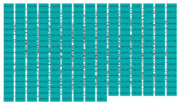
Grid Layout
The grid layout is a simple layout the arranges all of the nodes in a square grid. This is the default layout and is always available as part of the Cytoscape core. It is available by selecting Layout → Grid Layout. A sample screen shot is shown above.
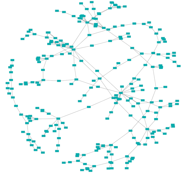
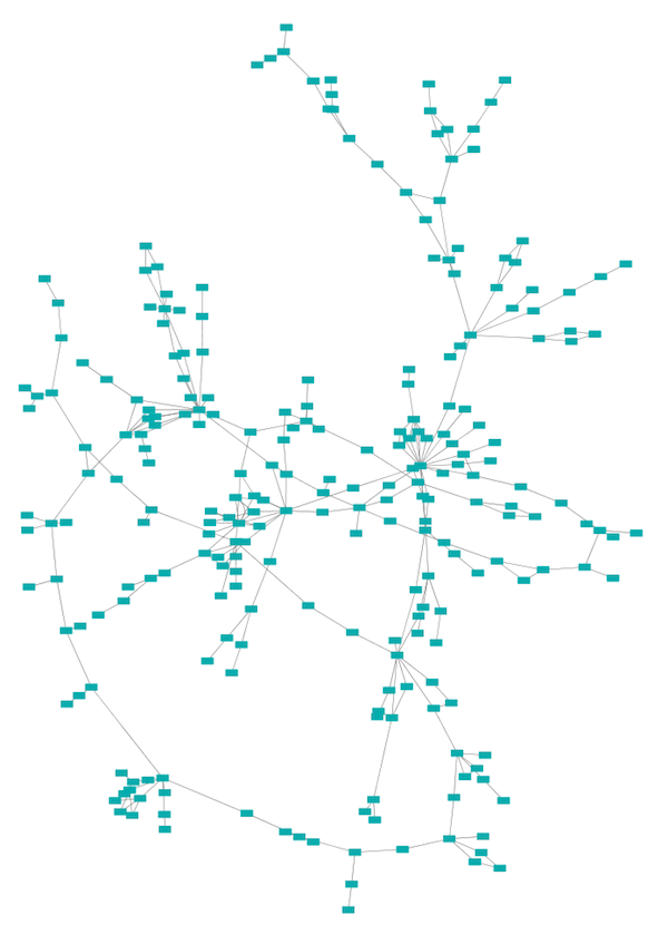
Edge-weighted Spring-Embedded Layout
The spring-embedded layout is based on a “force-directed” paradigm as implemented by Kamada and Kawai (1988). Network nodes are treated like physical objects that repel each other, such as electrons. The connections between nodes are treated like metal springs attached to the pair of nodes. These springs repel or attract their end points according to a force function. The layout algorithm sets the positions of the nodes in a way that minimizes the sum of forces in the network. This algorithm can be applied to the entire network or a portion of it by selecting the appropriate options from Layout → Edge-weighted Spring Embedded.
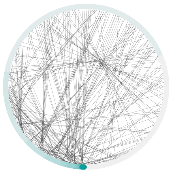
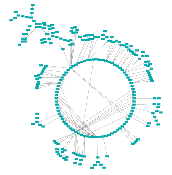
Attribute Circle Layout
The Attribute Circle layout is a quick, useful layout, particularly for small networks, that will locate all of the nodes in the network around a circle. The node order is determined by a user-selected node column. The result is that all nodes with the same value for that column are located together around the circle. Using Layout → Attribute Circle Layout → column to put all nodes around a circle using column to position them. The sample screen shot above shows the a subset of the galFiltered network organized by node degree.
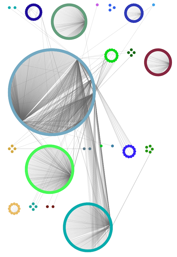
Group Attributes Layout
The Group Attributes layout is similar to the Attribute Circle layout described above except that instead of a single circle with all of the nodes, each set of nodes that share the same value for the column are laid out in a separate circle. The same network shown above (network generated by PSICQUIC Client) is shown above, using Layout → Group Attributes Layout → taxonomy.
Prefuse Force Directed Layout
The force-directed layout is a layout based on the "force-directed" paradigm. This layout is based on the algorithm implemented as part of the prefuse toolkit provided by Jeff Heer. The algorithm is very fast and with the right parameters can provide a very visually pleasing layout. The Force Directed Layout will also accept a numeric edge column to use as a weight for the length of the spring, although this will often require more use of the Settings... dialog to achieve the best layout. This algorithm is available by selecting Layout → Prefuse Force-Directed Layout → (unweighted) or the edge column you want to use as a weight. A sample screen shot showing a portion of the galFiltered network provided in sample data is provided above.
yFiles Layouts
yFiles layouts are a set of commercial layout algorithms which are provided courtesy of yWorks. Due to license restrictions, the detailed parameters for these layouts are not available (there are no yFiles entries in the Layout → Settings...). The main layout algorithms provided by yFiles are:
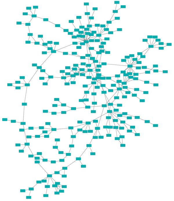
yFiles Organic Layout
The organic layout algorithm is a kind of spring-embedded algorithm that combines elements of the other algorithms to show the clustered structure of a graph. This algorithm is available by selecting Layout → yFiles Layouts → Organic.
yFiles Circular Layout
This algorithm produces layouts that emphasize group and tree structures within a network. It partitions the network by analyzing its connectivity structure, and arranges the partitions as separate circles. The circles themselves are arranged in a radial tree layout fashion. This algorithm is available by selecting Layout → yFiles Layouts → Circular.
yFiles Hierarchical Layout
The hierarchical layout algorithm is good for representing main direction or "flow" within a network. Nodes are placed in hierarchically arranged layers and the ordering of the nodes within each layer is chosen in such a way that minimizes the number of edge crossings. This algorithm is available by selecting Layout → yFiles Layouts → Hierarchical.
Layout Parameters
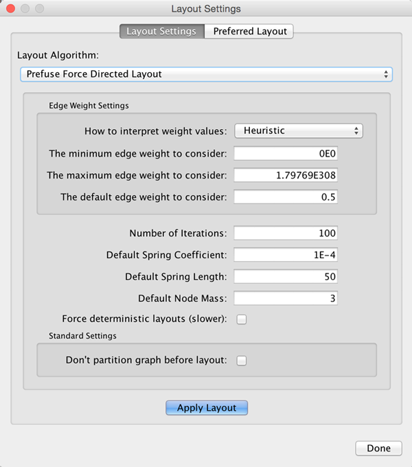
Many layouts have adjustable parameters that are exposed through the Layouts → Settings... menu option. The Layout Settings dialog, which allows you to choose which layout algorithm settings to adjust, is shown below. The settings presented vary by algorithm and only those algorithms that allow access to their parameters will appear in the drop-down menu at the top of the dialog. Once you've modified a parameter, clicking the Execute Layout button will apply the layout.
Edge Bend and Automatic Edge Bundling
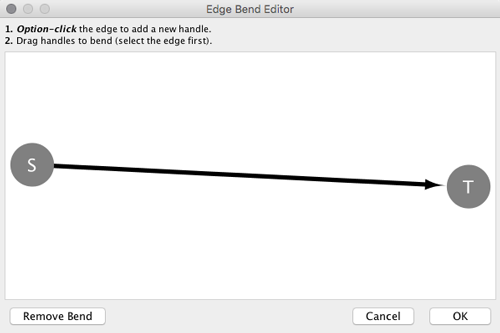
From Cytoscape 3.0, Edge Bend is a regular edge property and can be used as a part of a Style. Just like any other edge property, you can select a Default Value, a Mapping and use Bypass for select nodes. In the Styles tab, select the Bend property from the Properties drop-down and click on either the Default Value, Mapping or Bypass cell to bring up the Edge Bend Editor. In the editor, you can add as many handles as you want to the edge using Alt-Click on Windows, Option-Click on Mac, or Ctrl-Alt-Click on Linux.
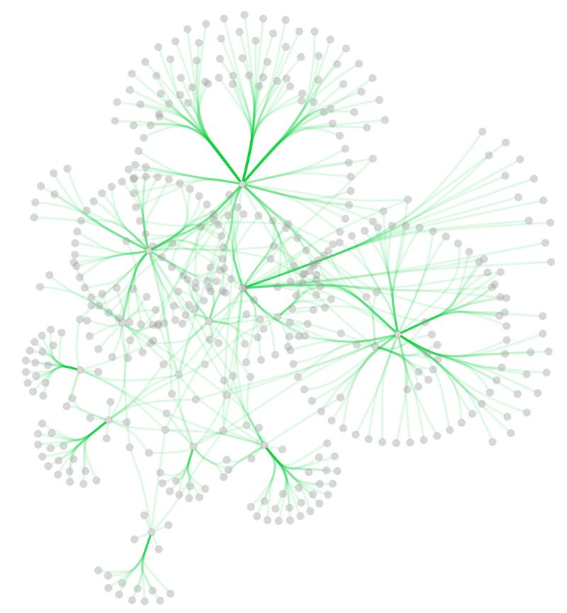
To clear all edge bends, select Layout → Clear All Edge Bends.
In addition to adding handles manually, you can use the Bundle Edges function to bundle all or selected edges automatically.
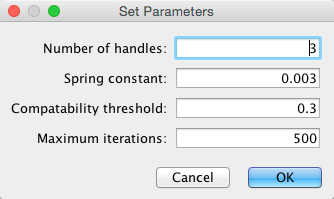
Select Layout → Bundle Edges → All Nodes and Edges.
- Set parameters.
Details of the algorithm is described in this paper.
- Press OK to run. Edge bundling may take a long time if the number of edges is large.
If it takes too long, try decreasing Maximum Iterations.
For large, dense networks, try setting Maximum iterations in the range of 500 - 1000.
Note: The handle locations will be optimized for current location of nodes. If you move node positions, you need to run the function again to get proper result.
Manual Layout
The simplest method to manually organize a network is to click on a node and drag it. If you select multiple nodes, all of the selected nodes will be moved together.
Rotate
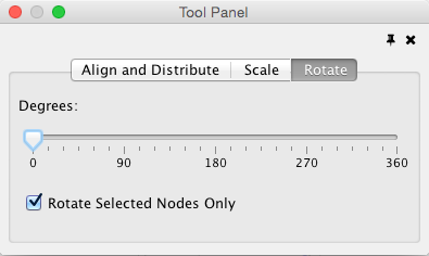
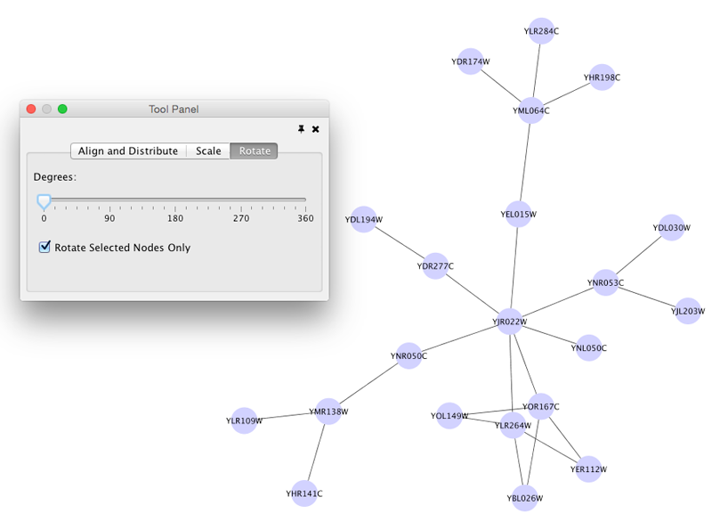
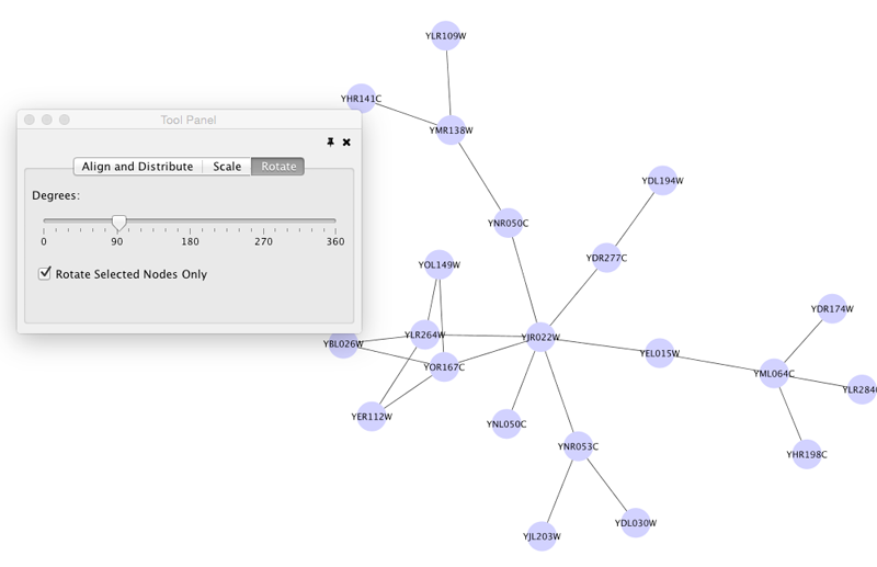
Selecting the Layout → Rotate option will show the Rotate window in the Tool Panel. This function will either rotate the entire network or a selected portion of the network. The image below shows a network with selected nodes rotated.
Before
After
Scale
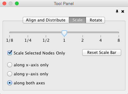
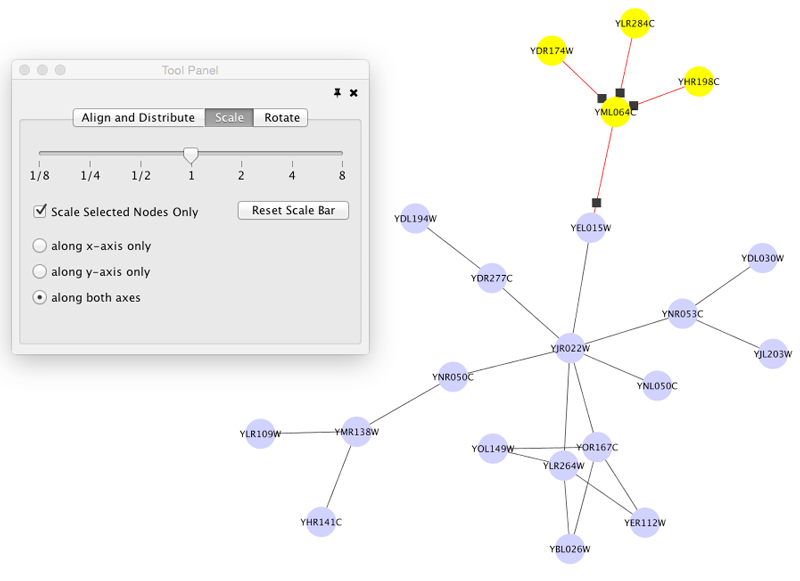
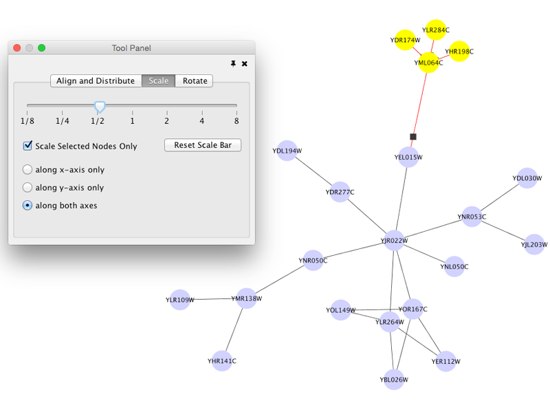
Selecting the Layout → Scale option will open the Scale window in the Tool Panel. This function will scale the position of the entire network or of the selected portion of the network. Note that only the position of the nodes will be scaled, not the node sizes. Node size can be adjusted using Styles. The image below shows selected nodes scaled.
Before
After
Align, Distribute and Stack
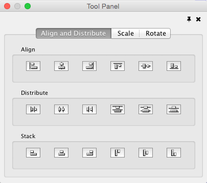
Selecting the Layout → Align/Distribute option will open the Align and Distribute window in the Tool Panel. Align provides different options for either vertically or horizontally aligning selected nodes against a line. The differences are in what part of the node gets aligned, e.g. the center of the node, the top of the node, the left side of the node. Distribute evenly distributes selected nodes between the two most distant nodes along either the vertical or horizontal axis. The differences are again a function what part of the node is used as a reference point for the distribution. Stack vertically or horizontally stacks selected nodes with the full complement of alignment options. The table below provides a description of what each button does.
Button |
Before |
After |
Description of Align Options |
|
|
|
Vertical Align Top - The tops of the selected nodes are aligned with the top-most node. |
|
|
|
Vertical Align Center - The centers of the selected nodes are aligned along a line defined by the midpoint between the top and bottom-most nodes. |
|
|
|
Vertical Align Bottom - The bottoms of the selected nodes are aligned with the bottom-most node. |
|
|
|
Horizontal Align Left - The left hand sides of the selected nodes are aligned with the left-most node. |
|
|
|
Horizontal Align Center - The centers of the selected nodes are aligned along a line defined by the midpoint between the left and right-most nodes. |
|
|
|
Horizontal Align Right - The right hand sides of the selected nodes are aligned with the right-most node. |
Button |
Before |
After |
Description of Distribute Options |
|
|
|
Vertical Distribute Top - The tops of the selected nodes are distributed evenly between the top-most and bottom-most nodes, which should stay stationary. |
|
|
|
Vertical Distribute Center - The centers of the selected nodes are distributed evenly between the top-most and bottom-most nodes, which should stay stationary. |
|
|
|
Vertical Distribute Bottom - The bottoms of the selected nodes are distributed evenly between the top-most and bottom-most nodes, which should stay stationary. |
|
|
|
Horizontal Distribute Left - The left hand sides of the selected nodes are distributed evenly between the left-most and right-most nodes, which should stay stationary. |
|
|
|
Horizontal Distribute Center - The centers of the selected nodes are distributed evenly between the left-most and right-most nodes, which should stay stationary. |
|
|
|
Horizontal Distribute Right - The right hand sides of the selected nodes are distributed evenly between the left-most and right-most nodes, which should stay stationary. |
Button |
Before |
After |
Description of Stack Options |
|
|
|
Vertical Stack Left - Vertically stacked below top-most node with the left-hand sides of the selected nodes aligned. |
|
|
|
Vertical Stack Center - Vertically stacked below top-most node with the centers of selected nodes aligned. |
|
|
|
Vertical Stack Right - Vertically stacked below top-most node with the right-hand sides of the selected nodes aligned. |
|
|
|
Horizontal Stack Top - Horizontally stacked to the right of the left-most node with the tops of the selected nodes aligned. |
|
|
|
Horizontal Stack Center - Horizontally stacked to the right of the left-most node with the centers of selected nodes aligned. |
|
|
|
Horizontal Stack Bottom - Horizontal Stack Center - Horizontally stacked to the right of the left-most node with the bottoms of the selected nodes aligned. |
Node Movement and Placement
In addition to the ability to click on a node and drag it to a new position, Cytoscape now has the ability to move nodes using the arrow keys on the keyboard. By selecting one or more nodes using the mouse and clicking one of the arrow keys (←, →, ↑, ↓) the selected nodes will move one pixel in the chosen direction. If an arrow key is pressed while holding the Shift key down, the selected nodes will 15 pixels in the chosen direction.
