|
Size: 3612
Comment:
|
← Revision 8 as of 2009-02-12 01:03:51
Size: 5276
Comment: converted to 1.6 markup
|
| Deletions are marked like this. | Additions are marked like this. |
| Line 18: | Line 18: |
| [[TableOfContents([2])]] | <<TableOfContents([2])>> |
| Line 36: | Line 36: |
| attachment:cleavage1_061115_dwk.png | {{attachment:cleavage1_061115_dwk.png}} |
| Line 54: | Line 54: |
| attachment:cleavage2_061115_dwk.png | {{attachment:cleavage2_061115_dwk.png}} |
| Line 64: | Line 64: |
| [[PageComment2]] |
AllanKuchinsky - 2006-11-17 03:28:19 Rendering of the phosphorylated species could be handled via the current vizmapper functionality, mapping an attribute signifying phosphorylation to a Node label, Node color, and Node line type. Possible minor enhancements to the vizmapper and renderer may be needed to support values of "no border" and "no node color". ---- AllanKuchinsky - 2006-11-28 05:11:31 Actually, there may not be a 1-1 mapping between nodes in the model and nodes in the view. In the topmost figure, is node3 (unphosphorylated A) only implicit in the view? If that is the case, should node3 be only implicit in the model, as well? But what if node3 is involved in a subsequent interaction? How is that currently represented in MIMs? ---- AllanKuchinsky - 2006-11-28 05:17:37 It appears as if cleavage between domains is a new use case for GroupAPI and may require extensions to the group model, as well as changes to the view. I will write this up as a use case for GroupAPI. ---- AllanKuchinsky - 2006-11-29 04:25:22 Per cleavage between domains (and discussion with Scooter Morris), we might want to introduce the context of a 'site' for a CyNode, which could be used to represent cleavage sites, splice junctions, and other sub-node entities. In the model, this could be implemented via the Group, each 'site' being a child of the group. In the view, this could be represented as a 1-pixel wide rectangle adjacent to the border of the node, or perhaps a 1-pixel square rectangle at a point on the node. This may constitute a re-invention of the construct of a 'port' in the Cytoscape context. |
Use Case Name : ../ShowCleavage |
For Feature : MIM Editor |
Editors: DavidKane |
<<TableOfContents: execution failed [Argument "maxdepth" must be an integer value, not "[2]"] (see also the log)>>
Summary
A user wants to describe the possibility that a covalent bond can be cleaved.
Step-by-Step User Action
- User specifies a covalent bond that is to be cleaved
- User specifies a species that acts to cleave the bond
- User specifies that there is a cleaving relationship between the two
- User optionally specifies the evidence for this relationship
Visual Aides
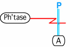
The Kohn notation for this binding is the following. The species that is cleaving the bond is on end of the edge. The other end of the edge goes across the bond that is being cleaved.

The color in this example is convention, and is not an essential element in the notation.
Requirements for Cytoscape
This could be modeled as a hyperedge containing node1: Phtase (hyperedge attribute: enzyme), node2: phosphorylated A, node3: unphosphorylated A. The mapping might be different if it is a protein that is being cleaved. View: Use case for hyperedge view. Might require a new line type in Vizmapper.
Importance
This is important because it is a fairly common activity in the maps. In addition, it is an example of a reversal of another reaction.
Variations
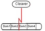
If the protein is modeled with details about ../ProteinDomains, it is also possible to specify that the protein itself is cleaved.

Other Examples
Comments
Shared ../MimEditorUseCaseComments
The BioPAX representation of this binding could be a Biochemical Reaction object (e.g. Biochemical Reaction object with Interaction-Type = "de-phosphorylation", Participants = AP,A,P, Left = AP, and Right = A,P, where A, AP and B are physicalEntities.)
AllanKuchinsky - 2006-11-17 03:28:19
Rendering of the phosphorylated species could be handled via the current vizmapper functionality, mapping an attribute signifying phosphorylation to a Node label, Node color, and Node line type. Possible minor enhancements to the vizmapper and renderer may be needed to support values of "no border" and "no node color".
AllanKuchinsky - 2006-11-28 05:11:31
Actually, there may not be a 1-1 mapping between nodes in the model and nodes in the view. In the topmost figure, is node3 (unphosphorylated A) only implicit in the view? If that is the case, should node3 be only implicit in the model, as well? But what if node3 is involved in a subsequent interaction? How is that currently represented in MIMs?
AllanKuchinsky - 2006-11-28 05:17:37
It appears as if cleavage between domains is a new use case for GroupAPI and may require extensions to the group model, as well as changes to the view. I will write this up as a use case for GroupAPI.
AllanKuchinsky - 2006-11-29 04:25:22
Per cleavage between domains (and discussion with Scooter Morris), we might want to introduce the context of a 'site' for a CyNode, which could be used to represent cleavage sites, splice junctions, and other sub-node entities. In the model, this could be implemented via the Group, each 'site' being a child of the group. In the view, this could be represented as a 1-pixel wide rectangle adjacent to the border of the node, or perhaps a 1-pixel square rectangle at a point on the node.
This may constitute a re-invention of the construct of a 'port' in the Cytoscape context.