|
Size: 3322
Comment:
|
← Revision 17 as of 2009-09-29 18:07:05
Size: 5273
Comment:
|
| Deletions are marked like this. | Additions are marked like this. |
| Line 38: | Line 38: |
| * Network Overview | |
| Line 39: | Line 40: |
| attachment: sample_modules.png |
{{attachment:sample_modules.png}} *Modules (A ~ D) {{attachment:moduleA.png}} {{attachment:moduleB.png}} {{attachment:moduleC.png}} {{attachment:moduleD.png}} |
| Line 45: | Line 53: |
| ===== SIF ===== | ===== Extended SIF ===== |
| Line 47: | Line 55: |
|
* child_of - Defines inclusion. * interact_with |
* '''''child_of''''' - Defines inclusion. * '''''interact_with''''' - interaction between modules. |
| Line 50: | Line 58: |
| We can mimic the terms used in semantic web. Relationship between modules can be |
The first column defines edge attribute for defining which module has the edge in the row. The sample graph above can be represented in the following: {{{ moduleB node7 DirectedEdge node3 moduleA node6 DirectedEdge node2 moduleD node5 DirectedEdge node4 moduleD node4 DirectedEdge node2 node4 DirectedEdge node3 moduleA node1 DirectedEdge node2 moduleC node1 DirectedEdge node0 moduleA node0 DirectedEdge node6 moduleA node0 DirectedEdge node2 moduleC child_of moduleA moduleD interact_with moduleA moduleD interact_with moduleB }}} |
| Line 57: | Line 83: |
|
subnet1 a b c subnet2 a d subnet3 c e f |
moduleA node0 node1 node2 node6 moduleB node3 node7 moduleC node0 node1 moduleD node2 node4 node5 |
| Line 62: | Line 89: |
|
==== Option 2: One File (extended SFI?) ==== (Not finished yet) |
Based on the information above, Cytoscape can rebuild the module relation map: {{attachment:moduleDAG.png}} Pros: simple and biologist-editable Cons: extra files needed The alternative is separate the first column of SIF, and read as a regular edge attribute. In this case, number of files is three. ==== Option 2: One File (PSI-MI TAB 2.5-like table format) ==== This approach is similar to PSI-MI TAB 2.5. MI-TAB file contains both node and edge attributes in one file. For example, if we need to convert the data above into this format, it looks like this: {{{ part_of source source members interaction target target members moduleB node7 DirectedEdge node3 moduleA node6 DirectedEdge node2 moduleD node5 DirectedEdge node4 moduleD node4 DirectedEdge node2 node4 DirectedEdge node3 moduleA node1 DirectedEdge node2 moduleC node1 DirectedEdge node0 moduleA node0 DirectedEdge node6 moduleA node0 DirectedEdge node2 moduleC node0,node1 child_of moduleA node0,node1,node2,node6 moduleD node2,node4,node5 interact_with moduleA node0,node1,node2,node6 moduleD node2,node4,node5 interact_with moduleB node3,node7 }}} Pros: Only one file. Excel editable. Cons: Redundant module member information. |
Support for Modules in Cytoscape
Introduction
In many cases, biologists are interested in relationship between functional modules first. Then, they look into the details inside the modules, i.e., actual interactions. Cytoscape can partially handle this problem using Group API and some related plugins, but it's not a standard feature. Also, there is no simple file format to represent hierarchy/substructures. In this project, we are going to implement a mechanism to handle output of module finding algorithms as a hierarchy of subnetworks and make Cytoscape core module-aware.
Usecases
Module Finding Plugins
Currently, there are several plugins finding functional modules from large networks. In some cases, they produce subnetworks, but there is no universal UI or function to keep the structure in the session or other files.
Pathway Overview
Cytoscape has function to import KEGG/Reactome data as attributes. It is useful if Cytoscape has a function to generate substructure automatically based on such annotation.
Implementation
File Formats
Most of popular XML graph file formats support hierarchical structure.
DOT
This is a standard file format in graphviz. It has XML-like structure in the text file, and can represent substructure.
Pajek
This program has 3 types of files to represent substructure:
- Partitions – they tell for each vertex to which class vertex belong. Default extension: .clu.
- Clusters – subset of vertices (e.g. one class from partition). Default extension: .cls.
- Hierarchies – hierarchically ordered vertices. Default extension: .hie.
Therefore, user needs to load 4 files (network, partition, cluster, hierarchy) to reconstruct the saved substructures.
igraph
This package does not have its own file format to represents subgraph. Instead, supporting GraphML and dot.
Cytoscape New File Format for Subgraphs
Standard XML file formats such as GraphML or XGMML can represent substructures. However, they are not easy to edit by hand for many biologists. We need to implement a simple table/text style file format which is editable on spreadsheet programs.
Sample
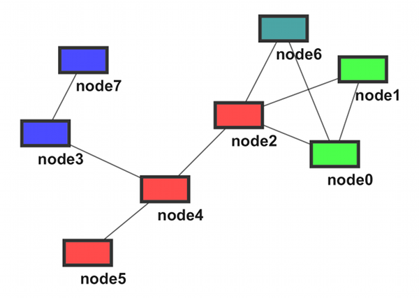
- Network Overview
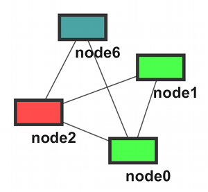
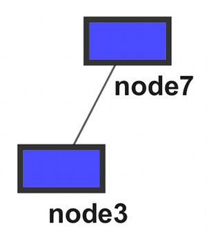
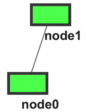
- Modules (A ~ D)
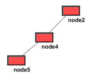
Option 1: Two Files
This approach needs two files, standard SIF file and subnetwork definition file (SDF?). This is similar to pajek, but less number of files are required to rebuild the substructures and hierarchies.
Extended SIF
We need to introduce two types of special value for interaction edge attributes:
child_of - Defines inclusion.
interact_with - interaction between modules.
The first column defines edge attribute for defining which module has the edge in the row.
The sample graph above can be represented in the following:
moduleB node7   DirectedEdge    node3
moduleA node6   DirectedEdge    node2
moduleD node5   DirectedEdge    node4
moduleD node4   DirectedEdge    node2
        node4   DirectedEdge    node3
moduleA node1   DirectedEdge    node2
moduleC node1   DirectedEdge    node0
moduleA node0   DirectedEdge    node6
moduleA node0   DirectedEdge    node2
        moduleC child_of        moduleA
        moduleD         interact_with   moduleA
        moduleD         interact_with   moduleB
If parser finds these two keywords in interaction edge attribute, treat it as a module relationship definition.
SDF
This file defines members of each subnetwork.
moduleA node0 node1 node2 node6
moduleB node3 node7
moduleC node0 node1
moduleD node2 node4 node5
Based on the information above, Cytoscape can rebuild the module relation map:
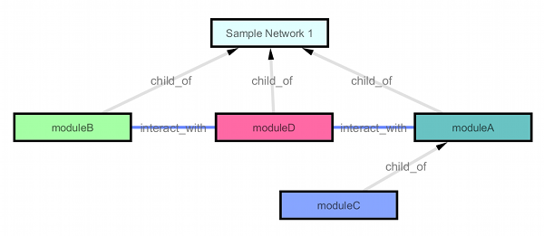
Pros: simple and biologist-editable Cons: extra files needed
The alternative is separate the first column of SIF, and read as a regular edge attribute. In this case, number of files is three.
Option 2: One File (PSI-MI TAB 2.5-like table format)
This approach is similar to PSI-MI TAB 2.5. MI-TAB file contains both node and edge attributes in one file. For example, if we need to convert the data above into this format, it looks like this:
part_of source  source members  interaction     target  target members
moduleB node7           DirectedEdge    node3
moduleA node6           DirectedEdge    node2
moduleD node5           DirectedEdge    node4
moduleD node4           DirectedEdge    node2
        node4           DirectedEdge    node3
moduleA node1           DirectedEdge    node2
moduleC node1           DirectedEdge    node0
moduleA node0           DirectedEdge    node6
moduleA node0           DirectedEdge    node2
        moduleC node0,node1     child_of        moduleA node0,node1,node2,node6
        moduleD         node2,node4,node5       interact_with   moduleA node0,node1,node2,node6
        moduleD         node2,node4,node5       interact_with   moduleB node3,node7
Pros: Only one file. Excel editable. Cons: Redundant module member information.
Option 3: Simply Support DOT
As far as I know, DOT is the most complete solution for non-XML file format for representing modules. If we support this format, we can use it to represent